A User’s Guide for Non Rocket Scientists (Part 2)
by Terry Burlison
Note: A glossary of terms is provided at the end of the article, as are two appendices: “Complications” (why all this is even harder than it sounds) and “Flight Lessons” (two historic missions where things didn’t go as planned).
In last month’s article we discussed rendezvous: that magical blend of art and science that enables us to figure out when to launch our spacecraft and how to maneuver it to the proximity of another vehicle already in orbit above the Earth. We flew an imaginary space shuttle rendezvous, culminating in a stand-off position some 40 miles (74 km) behind the International Space Station (ISS). The courtship phase of our mission is complete; now it’s time to get these vehicles to mate.
To do so, you must forget everything you know about how things move on Earth.
Imagine you’re the starting quarterback in the Super Bowl. You take the first snap from center, spy a receiver breaking into the open downfield, and loft a perfect pass that drops gently into his hands as he streaks toward the end zone. You’re up six-nothing and already making plans for that MVP trophy.
Not a likely scenario, admittedly, but one that’s easy to imagine.
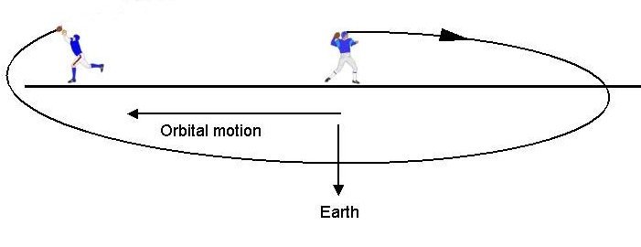
Now, let’s move that game into the future: the first Super Bowl played in low Earth orbit. Players line up, hovering in zero gravity with their NFL jetpacks. The center snaps the ball, you see the receiver open far ahead, and once more you loft the football in his direction. This time however, the ball continues to climb, moving higher and higher above the playing field. Worse, the ball also starts slowing down as it gains altitude. It stops moving forward entirely and, still climbing, begins gliding back toward the line of scrimmage! You stare in horror as the ball now flies backward, far over your head, picking up speed as it hurtles out of the stadium behind you! The game is only a few minutes in, you’re already down two-nothing, and the world is laughing at you. What went wrong?
Welcome to the Alice in Wonderland world of orbital mechanics.
Conservation: It's not just a good idea; it's the law
Back in school you probably learned about something called “conservation of energy,” and perhaps immediately forgot about it. What relevance could it have to daily life?
Well, a lot. And not only for astronauts.
The conservation principle essentially says that the energy in a closed system is constant: it can be neither created nor destroyed, only converted. To change the energy of a system you must either add to it from outside or transfer it to a different system. For this discussion, we’ll talk about three basic kinds of energy: chemical, kinetic, and potential.
Chemical is easy to understand—it’s the energy stored in the chemistry of a substance, such as batteries, gasoline, or rocket propellants. Converting it into usable energy is as easy as flipping a switch or lighting a match.
Kinetic is pretty straightforward as well—the energy of a moving object. Look at a car after a head-on collision and you can see how much energy the vehicle had prior to impact!
Potential energy is a bit harder to understand. It’s the energy stored in an object by its physical relationship to an electromagnetic or (in our case) gravitational field. Moving an object farther from the center of the Earth, for example, increases its potential energy. You can demonstrate this with a fun experiment right in your own home!
Drop an egg on to your floor from a millimeter; it probably won't even crack. Now increase that egg’s potential energy by raising it over your head. (This, too, is energy transfer: to the egg from your muscles, which in turn came from your food, which in turn came from the Sun, etc.) Now, drop the egg. All that new potential energy gets converted into kinetic energy and, upon impact, is transferred to the planet Earth, much to the dismay of the egg.
Let’s apply these principles to space flight.
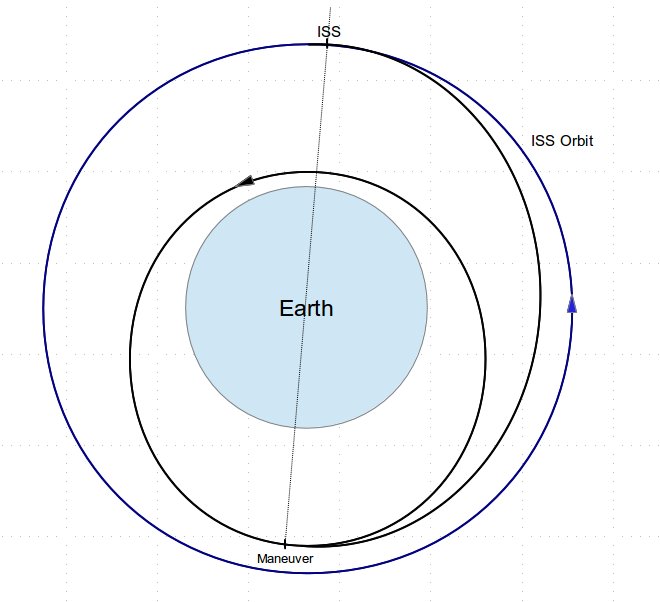
The booster rocket converts a massive amount of chemical energy into kinetic and potential to get the spacecraft into orbit. Once the spacecraft separates from the booster, it has a fixed amount of energy—a combination of its altitude (potential) and speed (kinetic). This total energy does not change as the spacecraft moves around its orbit! At perigee, the vehicle is closest to the Earth (lowest potential energy) and thus travels at its fastest speed (highest kinetic energy). As the craft drifts upward toward apogee, it trades off that speed for altitude, slowing down as it climbs.
Figure 1: Energy in an orbit remains constant
Higher orbits have more energy (and longer orbital periods) than lower orbits. Thus, the ISS at 210 nm (388 km) has more energy than a chaser vehicle at 110 nm (204 km). Since we don’t live in the Star Trek universe, we can’t instantaneously transport to a higher altitude—the only way to get to the ISS is to add kinetic energy via the chemical energy in the fuel. In other words, fire the engines.
So we execute our maneuver, increasing our speed and raising the opposite side of our orbit. Let's assume we're going up to the ISS altitude. Quick quiz: When we get to apogee (210 nm), will we be going faster, slower, or the same speed as the ISS?
We’re at the same altitude so we have the same potential. But since our overall orbit has less total energy, our kinetic energy (speed) must be slower than the ISS. Therefore, we have to thrust forward, adding speed, to match the orbit (and therefore the energy) of the ISS.
Still awake? Good, because this is where things get weird.
Curiouser and Curiouser
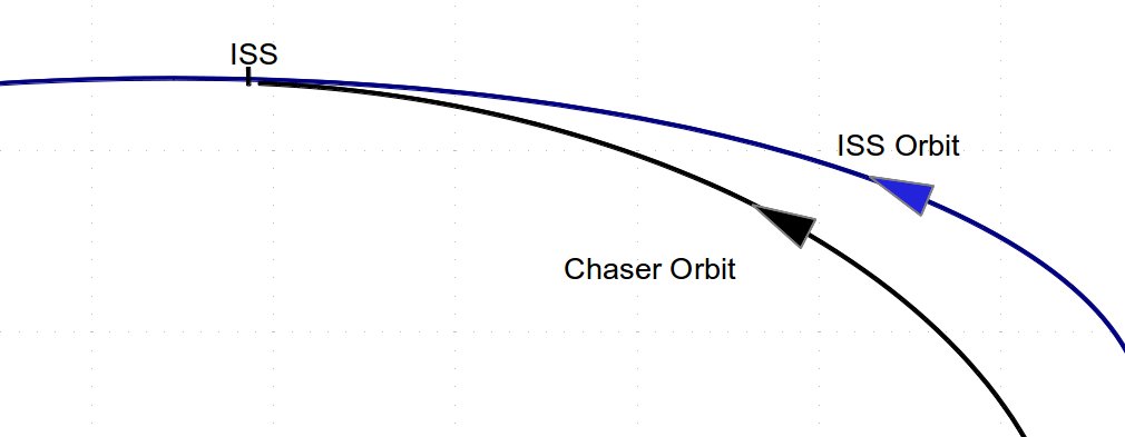
An inertial view of our approach orbit, from a fixed distance away, looks like this:
Figure 2: Approach shown in inertial space
Remember our relative coordinate system we introduced last time? It's centered at our target vehicle (in this case, the ISS), the “down” axis is always pointing at the center of the Earth (yes, positive is actually downward), “ahead” is along our direction of motion, and “sideways” is perpendicular to both. This is the way we humans see the world: centered at ourselves (of course), down is “down,” and ahead is “ahead.”
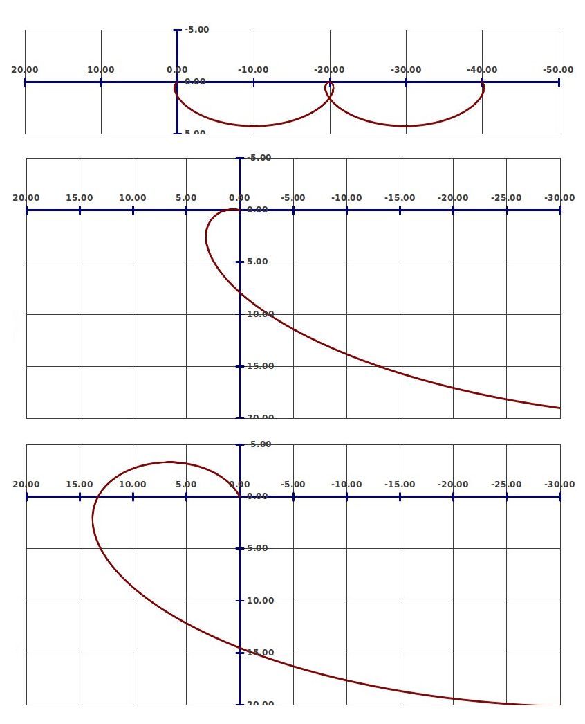
Thus, you might think that when viewed by the astronauts, the approach to the ISS would look something like this:
Figure 3: NOT how an approach really looks!
In fact, it looks like this:
Figure 4: How an approach really looks
Rather than approaching from behind and below, we’re closing from ahead. Why? Two reasons.
First, remember our discussion of energy. As you recall, when we reach the ISS altitude, we are traveling slower than the ISS. That means that we will appear to be “backing up” as we get close to it!
Imagine trying to park your car this way. You approach the parking spot (which you think is standing still, cooperatively awaiting your arrival), but as you approach, it suddenly starts accelerating ahead of you. To get in the spot, you have to anticipate this and aim for a point ahead of it so the parking slot will accelerate to a location under your car at the right moment!
Second, this relative coordinate system, called LVLH (local vertical, local horizontal) is rotating. Remember: down is always toward the center of the Earth. As you revolve 360° around the Earth in your orbit, you must also rotate 360° to keep the Earth below you. How does this impact what we're seeing out our windows?
Well, stand next to someone, then turn around. They will appear to move around you even though they're still standing in exactly the same place. (A few tequila shots can generate a similar effect.)
The combination of these two things—difference in energy (speed) in the two orbits and the rotating LVLH coordinate system—generates some truly bizarre “relative motion” plots. In fact, there are a lot of different approaches, but few look the way we'd expect.
Figure 5: Some different possible approaches
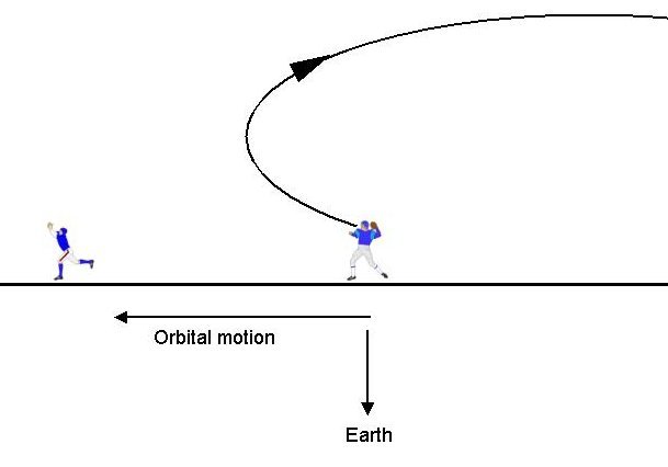
If you re-read the opening paragraphs of this article, you might now understand what happened to your perfect pass. You added kinetic energy to the ball by throwing it. The ball then had too much speed for its original orbit (the one you’re still in). So it started climbing. However, as it climbed it traded that kinetic energy for potential and slowed down. And kept slowing, until it was going slower than before you threw it! Thus, it began drifting backwards. Add to this the fact that the field you're on is rotating—keeping “down” toward the center of the Earth—the ball moves far above and behind you.
Figure 6: No Pro Bowl for you
So how do you actually complete the pass? You’d have to throw the ball backward! That would slow it down, so it now has too little energy for your orbit. It starts falling, trading potential for kinetic, meaning it will soon speed up, move ahead, and eventually climb back to the altitude where you threw it. (The pass also takes the entire first half to complete.)
Figure 7: Peyton Manning in orbit
Don't expect zero-gee football anytime soon.
Mating ritual
Now let’s finish the fictitious mission we started in my previous article.
In our last installment, we left you aboard an imaginary space shuttle. You had successfully rendezvoused with the ISS, at a point 40 nm (74 km) behind the ISS. Now it's time to approach.
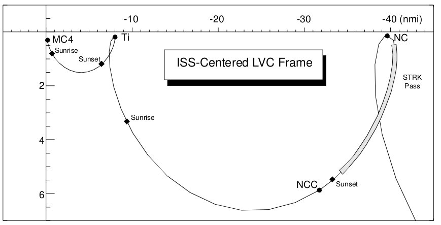
On Earth, if you want to approach an object in your car, you point the nose at it and press the gas. That's exactly not what we want to do now! Unlike the movie Gravity, we don’t just aim at the target and fire our thrusters. (One of approximately 42,000 technical flaws in the movie. Sorry, Mr. Clooney: it really is “rocket science.”) To approach the ISS, which is ahead of us, we slow down. This will drop us into an elliptical orbit with perigee below the ISS, meaning as we fall away from the station we will trade off enough potential energy for kinetic that we will start speeding up and moving toward it. Once we pass perigee, we will start climbing again, gradually slowing until we reach apogee, back at the ISS altitude. In fact, we end up in exactly the same relationship to the ISS we were immediately after the maneuver, except closer. How much closer depends on the maneuver: the more we slowed down, the farther ahead we'll move each orbit. We don’t want to attempt closing all the way in one shot, so we’ll aim for a closer point, eight miles (15 km) away.
Figure 8: Mid-range rendezvous approach
(Source: Rendezvous and Proximity Operations Design Reference for the International Space Station)
This NC, or phasing, maneuver is designed to bring the shuttle from its current position (40 nm) to a point near the ISS orbital altitude in exactly one orbit. Yep, we’re tearing through space at almost 18,000 mph, and it’s going to take us over an hour and a half to go 32 miles!
The NC maneuver occurs during a daylight pass, shortly before the vehicles plunge into darkness. This assures the Sun is “behind” the shuttle, brilliantly illuminating the ISS. Notice the gray patch labeled “STRK Pass” and the dot labeled “Sunset.” After the NC burn, the crew will use the shuttle’s star tracker to track the ISS, taking angle measurements on it exactly like they would on a star when aligning the inertial platform. Those angle measurements are then passed through a Kalman filter which, knowing the shuttle’s position, can accurately determine the ISS’s location relative to the shuttle, instead of to the center of the Earth.
Up to this point, the maneuvers have been computed on the ground, using two separate inertial state vectors (positions, velocities, and time) for the shuttle and the ISS. We now transition from the inertial phase of the rendezvous to the relative phase. As described in the last article, this is akin to using GPS to get you to the mall, but now you use your eyes to find the parking lot entrance.
During this star tracker pass, we take several “marks” to refine the estimate of the ISS position relative to us, and those data are then fed into our onboard targeting computer which then computes the next burns.
The next maneuver, shortly after entering darkness, is a “corrective combination” (NCC) burn. This important maneuver uses the star tracker updates to help us refine our trajectory, assuring us that we will hit exactly the right spot and to take out any planar error at the same time.
We use the star tracker because it gives us good estimates of the ISS position when we’re still some 40 nm distant. As we close to within about 14 nm (26 km), we come within range of our rendezvous radar (RR), a device that gives us extremely accurate range and range rate information. The RR will be the primary source of navigation data for the next few maneuvers.
We’ve now come out of darkness. The Sun has once again blazed into sight, and the ISS now gleams brilliantly only a few miles away. The radar has acquired it and further refined our next maneuver, the terminal phase initiation (TI) maneuver, which will occur around orbital “noon.”
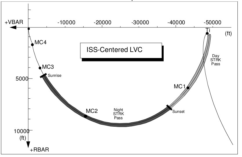
If we were having a problem on our vehicle or on the ISS, we could wave-off the TI burn; our shuttle would simply kiss the orbit of the ISS (almost) and we would immediately drop below it and move ahead, once more climbing to the ISS altitude one orbit later, but now some twenty-four miles ahead of it. (A requirement for visiting the ISS is that our coasting trajectory must never endanger the ISS, even in the event of a catastrophic failure.) But if all goes well, we will execute the TI burn on time and begin our terminal phase approach.
Figure 9: Post-TI trajectory
(Source: Rendezvous and Proximity Operations Design Reference for the International Space Station)
The terminal phase trajectory will not be perfect, so we plan a series of mid-course correction maneuvers (MC). We continue to track the ISS with our radar, constantly updating and tweaking those burns to make absolutely sure we are on the correct course. The TI burn is scheduled during a daylight pass so that if the RR has failed, we can use the star tracker as a backup (assuming the ISS isn’t so big and bright that it renders the ST useless). We pass into darkness again; now we are close enough to track a light on the ISS with our star tracker (Night STRK Pass). Another mid-course correction, if needed, then sunrise greets us with a fantastic view of the ISS, now only a mile away.
Two more mid-course tweaks and, we’re almost there!
Final Approach
We’ve just spent another orbit (about 90 minutes) closing from 8 nm to one, a blistering approach speed of about 5 mph—hardly faster than a brisk walk. Time to slow down!
To avoid slamming into the ISS in the event of a failure of some kind, we aimed for a point below it (on the “positive R-bar,” in NASA speak). As we approach this spot, about 600 feet (180 m) below the ISS, we have to make a decision: abort, fly around, or approach.
To abort, we do nothing; we will simply drift safely ahead and away. But we’re here to stay. While we could approach the ISS from any direction, the best, from an orbital mechanics standpoint, is from directly above or below, or from directly ahead or behind. These positions are on the positive and negative R-bar and positive and negative V-bar. (R-bar being the radius vector toward the center of the Earth and V-bar being essentially along the velocity vector of the ISS). We could do a maneuver to fly around the ISS to the positive V-bar or negative R-bar, but for this mission, we’ll go directly into an approach from below.
Figure 10: Shuttle approach corridors to the ISS
Being a certified orbital mechanic, you now realize this is not a stable position. We have lower energy than the ISS so our period is shorter, meaning we’ll start dropping and moving ahead if we do nothing. But a small burst of our rear-firing jets will propel us forward. Almost immediately, orbital mechanics will cause us to start to rise, moving up the R-bar.
Once we close to about 170’ (52 m), we stop to make sure everything is ready on our orbiter, on the ISS, and at Mission Control (both U.S. and Russian). The differential orbital mechanics effects are weak enough that we can stay on station for a while without burning up all our propellant. This is also a chance to confirm the huge solar arrays on the ISS are configured such that any jet firings in their direction won’t torque the entire station around.
(I was in mission control at a backroom support station for the STS-98 mission. The Atlantis waited and waited on the R-bar for the Russians to feather their solar arrays. Finally, the shuttle began to approach anyway. Sort of a game of cosmic chicken, I gathered. Finally, the Russians feathered their arrays. “It happens all the time,” a trajectory officer told me, shaking his head.)
Houston calls and gives us the “go” for approach. We fire the downward jets to start pushing us toward the station. Orbital mechanics slows us down (which is good) and causes us to fall backward (which is bad), so as we approach we have to keep tweaking the downward and rearward jets to keep us on centerline and moving upwards. This approach is preferred because orbital mechanics provides our braking: as we climb, we automatically slow down and don’t have to impinge the station with upward-firing jets as we would with a V-bar approach.
Figure 11: R-bar approach (no jets fire at ISS)
Figure 12: V-bar approach (jets fire at the ISS)
(Source: Rendezvous and Proximity Operations Design Reference for the International Space Station)
You may have seen movies where the shuttle (or another spacecraft) comes barreling in, screeching to a halt just as the docking mechanisms touch (<cough> Armageddon <cough>).
Not exactly.
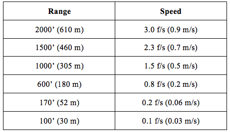
As we approach the station, our speed is constrained by a series of “braking gates” to assure we don’t inadvertently crash into the station. (<cough> Progress <cough>). These speed limits look like this:
That Fast and Furious five mph terminal segment is behind us. We’ll stop again at around 30’ before finally closing.
From here on in the differential orbital mechanics are so weak we can pretty much ignore them and thrust directly toward our goal, tweaking our course as needed. During this phase of the approach, all of our previous sensors are useless. The ISS became too big and bright for the star tracker miles ago. The rendezvous radar pings now bounce all over the structure, giving us wildly erratic readings. So how do we now estimate our range, rates, and angles?
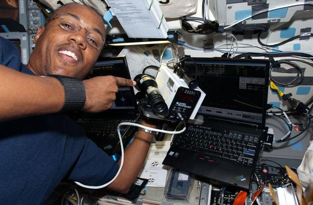
To provide data all the way to contact, NASA developed the Trajectory Control Sensor, (TCS). This device uses a laser radar to determine very precise range and range-rate. The shuttle also had cameras in the payload bay that showed the ISS on monitors in the crew cabin; the crew used overlays on the monitors to estimate their position and attitude. Additionally, the shuttle crew carried a hand-held lidar, or laser radar (HHL). Believe it or not, an astronaut would lie on his/her back, aim the laser through the overhead window, and bounce the laser off a selected spot on the ISS! This device would then measure the reflected beam and compute range and range-rate.
Figure 13: Astronaut Al Drew with the HHL (NASA archive image)
A former trajectory officer who requests anonymity recounts an interesting experience certifying the HHL:
We also flew Hand-Held Lidar (HHL) units. Essentially police laser guns. Funny thing is, everyone was scared of the TCS on the first docking mission so we used the HHL to verify and “certify” the TCS prior to docking. Years later, someone questioned the accuracy of the HHL and they used the TCS data to validate/certify the HHL! Classic.
In total, that final 600’ takes us the better part of an hour. Had we been racing a three-toed sloth, the sloth would have gotten to the station, devoured their entire onboard supply of freeze-dried fruit, and be fast asleep before we arrived.
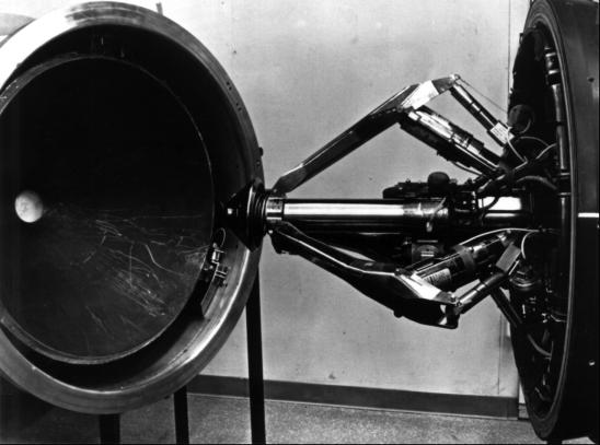
Typically, two spacecraft in orbit join by docking: one vehicle has a male (“probe”) segment and the other a female (“drogue”) receptacle. The pilot glides himself to within a few inches of his goal, and once he’s certain everything is properly aligned thrusts his probe firmly into the awaiting drogue. This triggers a set of latches, and the two craft snuggle together. (Who says rocket science isn’t sexy?)
Figure 14: Apollo-era “probe and drogue” (NASA archive photo)
For the 1975 Apollo-Soyuz Test Project (ASTP), NASA developed the Androgynous Peripheral Attach System, or APAS. This “androgynous” system gave both vehicles similar equipment, preventing a Cold War “who’s on top” argument. The space shuttle used a variant of the APAS for flights to the Russian Mir space station, and again to dock with the Russian segment of the ISS.
Figure 15: ASTP "androgynous" docking adapter (NASA archive image)
For ISS, a debate raged: docking in the traditional manner, or berthing—using the remote manipulator arm to bring the vehicles together. A source recalls:
There were lots of studies and many designs (from new to resurrecting the Apollo/Soyuz mechanism) but honestly, no one had money to build one. The station [program] wanted shuttle to pay and vice versa. Docking was probably preferred but it was really expensive and people kept saying “just berth it, it only costs you a grapple pin somewhere.” This kept the fighting going for years.
Since the Russians already had a docking adapter we could purchase and modify for far less money than developing our own, docking finally won the day.
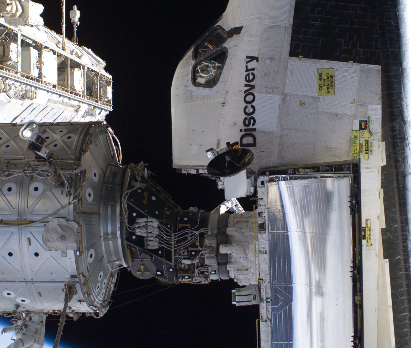
So we crawl to within 30’ of the ISS, snailing in at 0.1 fps. Twenty feet. The TCS is firing, giving us range and rates. Ten feet. A crew member lies on her back, firing the HHL for redundancy. The commander stares at a monitor at the aft crew station, watching the feed from a camera mounted along the centerline of our docking adapter, his hand on the controllers. Another astronaut switches out overlays as we approach. Finally, our pressurized mating adapter (PMA) nudges against its counterpart on the ISS. The commander fires thrusters to shove the vehicles together with enough force to engage the PMA latches. The shuttle is pulled snug against the ISS, vibrates for a moment, and is still.
Houston, we have arrived!
Figure 16: Shuttle docked at ISS via the PMA. Note the orientation dots affixed to the ISS, and the shuttle’s rendezvous radar dish next to name. (NASA archive image)
Journey’s end
Our trip lasted only a few days, but was the result of decades of planning, practice, and experience and of many mistakes and many improvements. Rendezvous, prox ops, and docking required inventing entirely new areas of orbital mathematics, new software, new sensors, new procedures. Without that Herculean effort, no humans would be living in space, no footprints would decorate the surface of the Moon. The fact that it has become so commonplace is a testament to the ingenuity and dedication of scientists, engineers, and pilots—experience that will serve us well as we open paths to the rest of the solar system.
(Of course, that’s after we figure out deep space hyperbolic rendezvous. And proximity operations in orbits around other worlds. And docking mechanisms that can survive months on the Martian surface. And . . .)
Figure 17: When it all goes right: shuttle at ISS
The following two appendices describe “real-world” complications not discussed so far, and two missions where things went wrong, told from the mission commanders’ perspectives.
APPENDIX A: Complications (Warning: science ahead!)
This section is for space geeks and hairy-knuckled engineers who, in lieu of a normal life, enjoy math, science, and spaceflight arcana. You can skip this section and suffer no irreparable harm.
A rendezvous plan is designed in advance, assuming everything will go more-or-less according to plan. But once the vehicle is actually on-orbit, things change. To update the rendezvous plan during the mission, engineers have to know several things, including where the two vehicles are now, and where they will be in the future. An object’s future location essentially depends on three things: its current location, how fast it’s moving (and in what direction), and the accelerations it will undergo.
Determining a spacecraft’s location and velocity (and attitude, the direction its pointing) is called navigation. If you think it’s easy, you’re wrong. If you think it’s hard, you’re still wrong. It’s really, really hard.
Where am I?
On the ground, we can navigate simply by looking around. Need better accuracy? Measure your location relative to a fixed object, such as a signpost, with a measuring tape or rangefinder. Or use GPS, which will tell you your location to within a few feet.
It’s not so easy in space. While GPS has vastly improved spacecraft navigation, until recently it was considered experimental. After all, GPS was designed and optimized for terrestrial applications, not for vehicles flying hundreds of miles up in space and traveling at many thousands of miles per hour. For spacecraft without GPS (including Gemini, Apollo, and even shuttle), the problem is much more difficult.
Navigation starts on the launch pad, where engineers know the spacecraft’s location with a high degree of accuracy and load that information into the vehicle’s computer. But how does the spacecraft know where it is once the engines ignite and blast it into and beyond the atmosphere?
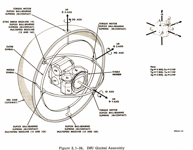
A spacecraft’s computer doesn’t just look around and “see” where it is; instead, it uses an inertial navigation system (INS). This typically includes sets of gyroscopes and accelerometers, called Inertial Measurement Units (IMU). An IMU cannot directly measure a vehicle’s location, nor can it measure the vehicle's speed, but it can sense accelerations. During flight, the INS uses (integrates) these accelerations to constantly estimate the vehicle’s new velocity, position, and attitude.
Figure 18: Inertial Measuring Unit (Apollo Lunar Module)
Imagine waking up in a car traveling down a very smooth, quiet highway at a constant speed. If you keep your eyes closed, you not only have no idea where you are, you can’t even tell which way you’re pointed or how fast you’re going. However, if you start from a known location, say your driveway, and are very, very good at sensing acceleration and change of direction (which is also an acceleration), and if you have a good sense of time, you could keep a very rough idea of your position and velocity. (“I’ve accelerated to about 40 mph, driven for ten minutes, then turned left.”) The better you can sense those accelerations and times, the better you can navigate. But of course over time your estimate will get worse.
So it is with an INS. At liftoff, the vehicle has an excellent estimate of its position, velocity, and attitude (known as its state), and the INS can sense acceleration in all three axes, both translational (forward/back, left/right, up/down) and rotational (roll, pitch, yaw). It will integrate these accelerations using its clock and determine its new velocity, then integrate that new velocity to estimate its current position and attitude. And it does this many times a second.
Whew. But as with our fictional car passenger, its estimate gets worse with time. Errors creep in. The platform soon isn’t even sure which way its gyroscopes are pointing, meaning all those integrated accelerations are slightly wrong.
Astronauts can “re-align” the INS gyroscopes by using the star tracker to measure the angles to the stars. But that doesn’t fix the errors already accrued in the vehicle state. That task is one of Mission Control’s most important jobs: the state vector update.
From the moment the vehicle launches, it is tracked by various radars: C-band (skin track), S-band (radar/transponder), satellite (TDRS), etc. These radars send signals to the vehicle and then listen for the response. Depending on the system, they can measure the angles to the target, the time it took the signal to get there and back (range), and the amount the signal has Doppler shifted (range rate). These data tell the tracking station the vehicle’s location in the sky, its distance away, and its relative speed (how fast it’s approaching or separating from the tracking station). By filtering that data, computers can, over time, come up with extremely accurate estimates of the vehicle’s state.
Flight controllers on the ground then compare that filtered state to the onboard state estimate, knowing the filtered state to be more accurate. When the onboard state has diverged by too much, the ground uplinks a new state vector (X, Y, Z, and Vx, Vy, Vz, and time, all relative to some predefined coordinate system) to the vehicle. This is called a state vector update and assures that the vehicle and the ground both agree on the spacecraft’s location and velocity.
The same process is carried out for the target vehicle.
So we’ve finished our state vector update and we know (pretty accurately) the locations of our two vehicles. Now we must predict where they will be in the future, so we can plan all those rendezvous maneuvers we discussed earlier. We can integrate these states forward in our computers, estimating all the forces (and subsequent accelerations) we anticipate they will undergo between maneuvers, and predict where they’ll be in the future. The accuracy of this ephemeris is highly dependent on our ability to model the forces that will act on our two spacecraft during flight.
How hard can that be?
Where am I going?
To this point, we’ve assumed a perfectly uniform, spherical Earth, devoid of atmosphere, Moon, Sun, or any other complications. Now we’re going to complicate matters. A lot.
First let’s consider this tenuous envelope of nitrogen, oxygen, and other gases called an atmosphere. While it’s exceedingly handy for life, it’s exceedingly nasty for trying to predict where objects in LEO will be in the future. As a vehicle plows through the atmosphere, the air molecules slam against its skin, slowing it down. This is true for softballs or space stations. This atmospheric drag is a function of the density of the atmosphere, the area, mass, shape, and orientation of the object traveling through it, and the square of that object’s speed.
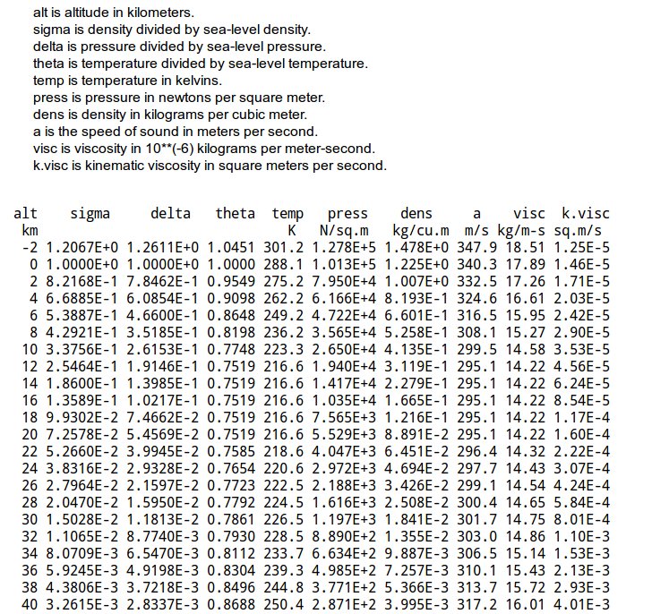
Atmospheric density is astonishingly difficult to compute. Many, many different mathematical models of the atmosphere have been advanced through the years, with arcane names like 1962 Standard, Jacchia 1970, Jacchia 1971 (aka CIRA72), NRLMSISE-00, and many others. All of them attempt to create a mathematical model or table that will estimate the density of the atmosphere, pressure, temperature, speed of sound, etc. at a given altitude.
Figure 19: A sample atmosphere table
An atmosphere model may also include location and date, because despite our earlier assumptions, the Earth is not a sphere (more on that later). It’s flattened, bulgy, with bumps and dips, and it’s spinning very fast. All these things effect the shape of the atmosphere. Additionally, the atmosphere changes shape and density with the seasons, even the time of day. On top of that, solar radiation from the Sun (which varies on a roughly eleven-year cycle) excites molecules in the atmosphere. During periods of high sunspot activity, the atmosphere “climbs,” extending its thin tendrils higher into space to clutch at spacecraft flying in low orbit. Atmosphere models attempt to quantify these effects.
Since drag is too tenuous to be sensed by our INS, it has to be modeled, historically in ground computers because of the complexity of the computations. But even though the magnitude of the drag is small, it acts constantly—and it really adds up. For an object in LEO, atmospheric drag can change a vehicle’s predicted location by dozens, even hundreds of miles in a single day! Thus the ongoing need for better atmosphere models.
One complication down.
Which way is up (or down)?
Gravity. We’re all familiar with it, this thing that holds us to Mother Earth and seems to get stronger each year (at least according to my scale). It’s easily measured, and it points straight down. Right?
Wrong on both counts.
In our earlier rendezvous discussion, we assumed the Earth was a sphere. It isn’t. Imagine taking a wad of clay, rolling it into a perfect ball between your hands, then placing it on a table. That’s a spherical Earth.
Now, put your palm on top of the ball and press down slightly, flattening the ball on the top and bottom and bulging it through the middle. That’s an oblate spheroid, and is much closer to the Earth’s shape. (In fact, the Earth is about 23 nautical miles (43 km) smaller in diameter through the poles than across the equator.)
But you aren’t done yet. Take your ball of clay and squeeze it in several other places, creating more, but smaller, bulges. Then add all kinds of dimples and dips to it, and press into it some heavier and lighter beads, so it’s no longer of a uniform density. Starting to get the picture?
The initial equatorial bulge you created is the dominant gravity perturbation that spacecraft encounter. For an equatorial orbit (0° inclination) or a polar orbit (90°), it has virtually no effect. But for the vast majority of low orbits, it’s a problem.
Imagine you’re onboard the ISS, whipping about the Earth at 210 nm (390 km) altitude and an inclination of 51.6°. As you pass the equator heading north, you ascend over the northern hemisphere. Were the Earth spherical, gravity would be straight down. However that equatorial bulge, now off to your right, means there is “more Earth” to your right than to your left! Therefore, gravity is not straight down, but pulling you ever so slightly to the right. When you pass the equator again, heading south, the bulge is now to your left, pulling you slightly in that direction.
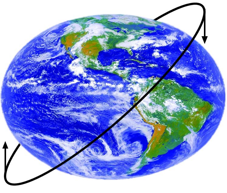
Figure 20: Nodal regression from torque produced by Earth's equatorial bulge
If you’ve never played with a gyroscope, you might guess that would change the inclination of the orbit. Nope. When a spinning object is pushed in one direction, it doesn’t tip: gyroscopic forces cause the object to nutate, in this case twisting the orbit around the equator. This is called nodal regression: a “node” being the point of an orbit that crosses the equator (ascending or descending), and “regression” because this equatorial bulge causes the orbit’s node to move to the west (usually), or “regress.”
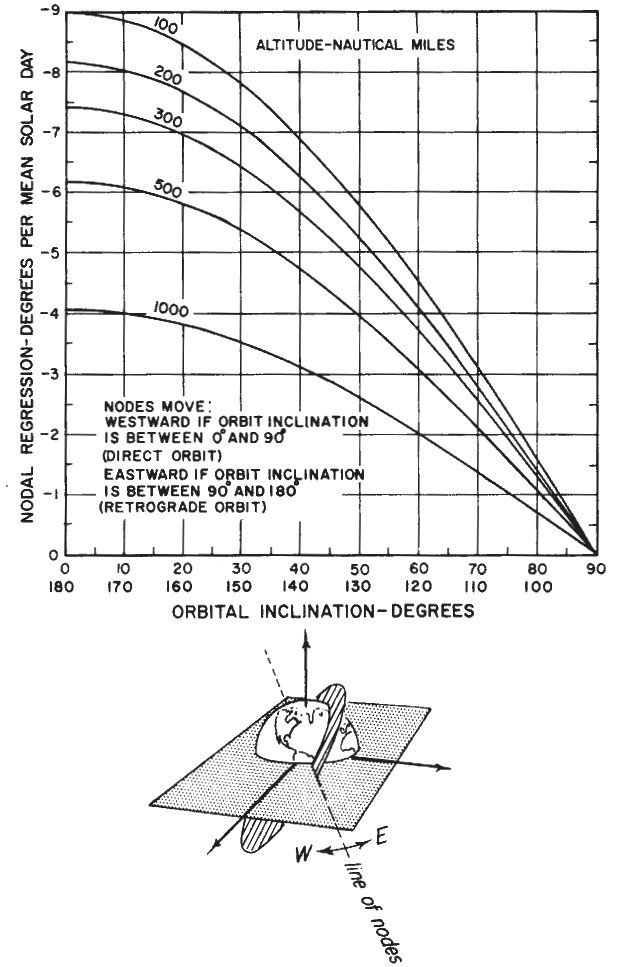
Figure 21: Nodal regression plot (Credit: Fundamentals of Orbital Dynamics by Bate, Mueller, and White)
Why is this such a problem? Because the amount of nodal regression depends on the inclination and altitude of the orbit. The implications of that statement provide a frightening realization for a novice mission planner: All those different orbits in the rendezvous plan will have different nodal regression rates from that of the ISS!
Is that really a big deal. Yep. Every day, the ISS orbit regresses about six degrees! During a rendezvous mission, this differential nodal regression can induce significant wedge angle errors between the vehicles’ planes.
Thus, the launch window code must drive the launch vehicle not to the ISS orbit plane, but to a “phantom plane” that is different, allowing the cumulative nodal regression in your mission plan to bring the chaser into the ISS orbit plane at the start of terminal phase. Remember that a launch delay changes the entire rendezvous plan, which changes the phasing orbit altitudes, which changes the differential regression, which changes the location of that phantom plane. Etc. etc. etc.
But it gets worse. Equatorial flattening, while the dominant complication, is only one issue. This misshapen ball we inhabit has other weird characteristics that must be modeled, such as zonal harmonics, tesseral harmonics, mass concentrations, and more. A full-up gravity model of the Earth is very complicated.
But unlike the atmosphere models, at least it doesn’t care about the Sun. Well . . .
The Sun’s gravity also impacts an orbiting vehicle. As does the Moon’s. As does solar radiance: the pressure of sunlight on the vehicle—which varies by the time of year and other factors.
But wait, there’s more! Every time our vehicle fires a maneuvering rocket, say to change attitude, it imparts not only a rotational acceleration to our craft, as intended, but also a translational acceleration. And in the name of fairness, the reverse is true: firing translational jets typically imparts rotational acceleration. This effect is called cross coupling and comes from the fact the jets cannot be perfectly aligned along the vehicle’s X,Y, and Z axes as well as pointing through the vehicle’s center of gravity. Besides, the center of gravity itself changes throughout the flight as payloads are deployed, propellant is burned, consumables are vented overboard, etc.
Speaking of consumables: every time we dump urine or waste water overboard, or otherwise “vent” any gases or liquids, more rotational and translational acceleration is imparted to our craft, thanks to Newton’s third law of motion.
The better we can model these effects, the better we can predict the maneuvers and plan (and execute) our rendezvous mission. For example, each orientation of our vehicle produces different drag, like holding your hand out a car window and twisting it. For that reason, Mission Control keeps an attitude timeline (ATL, pronounced “attle”) for their spacecraft: a chart of all expected attitudes throughout the mission, to be used for drag computations. They also maintain a vent timeline (VTL, pronounced “vittle”) so they know when vents or “dumps” will happen—liquids or gases expelled from the vehicle while on-orbit. Since all maneuvers, vents, and dumps change the mass and center of gravity (c.g.) of the vehicle, which then changes the drag and maneuver accelerations, they also keep a “mass properties” table: a chart of the vehicle’s mass and center of gravity for the entire mission.
Figure 22: Sample of shuttle venting events. A timeline of such events (the VTL) is used to improve the accuracy of the vehicle's ephemeris. (Source: Flight Dynamics Console Handbook, NASA)
So, roll all that together: atmosphere model, gravity model, ATL, VTL, mass properties, then combine it with all your estimates of the vehicle itself (engine performances and characteristics, estimated mass at lift-off, etc.), mix in your estimates of state from the onboard instruments or the ground, run it through a high-precision mathematical integrator (another source of error), and you generate your rendezvous timeline.
Repeat as needed, which is constantly.
APPENDIX B: Flight Lessons
As you have learned, rendezvous, proximity operations, and docking are among the most challenging tasks in space flight. It doesn't always go as smoothly as in our imaginary mission—a lesson NASA learned early and often.
Gemini 4: “I didn't have any idea in the world where we were”
NASA needed to master rendezvous and docking to go to the Moon, and Project Gemini was their test-bed. Gemini 4 (GT-4), the second manned Gemini mission, would demonstrate long-duration space flight with the crew, Jim McDivitt and Ed White, spending four days in the cramped capsule. NASA planners, however, decided the mission wasn't ambitious enough.
The Soviets had just performed world's first extravehicular activity (EVA), or “spacewalk.” So late in the mission planning phase for GT-4, NASA planners decided to add a spacewalk to the mission. As if that wasn't challenging enough, mission planners also decided at the last minute to use GT-4 to demonstrate on-orbit station-keeping.
From his home in Arizona, Gen. McDivitt, describes NASA's first attempt at on-orbit proximity operations:
“Towards the end of our training, and I mean really towards the end, they decided to do an EVA. And to make the EVA look like it was doing something, they decided to add [an experiment] to the upper stage of the Titan. I was going to fly over, and Ed was going to run over [using his hand-held maneuvering unit] and recover it, see how it was affected by launch. . . . It was completely ridiculous.”
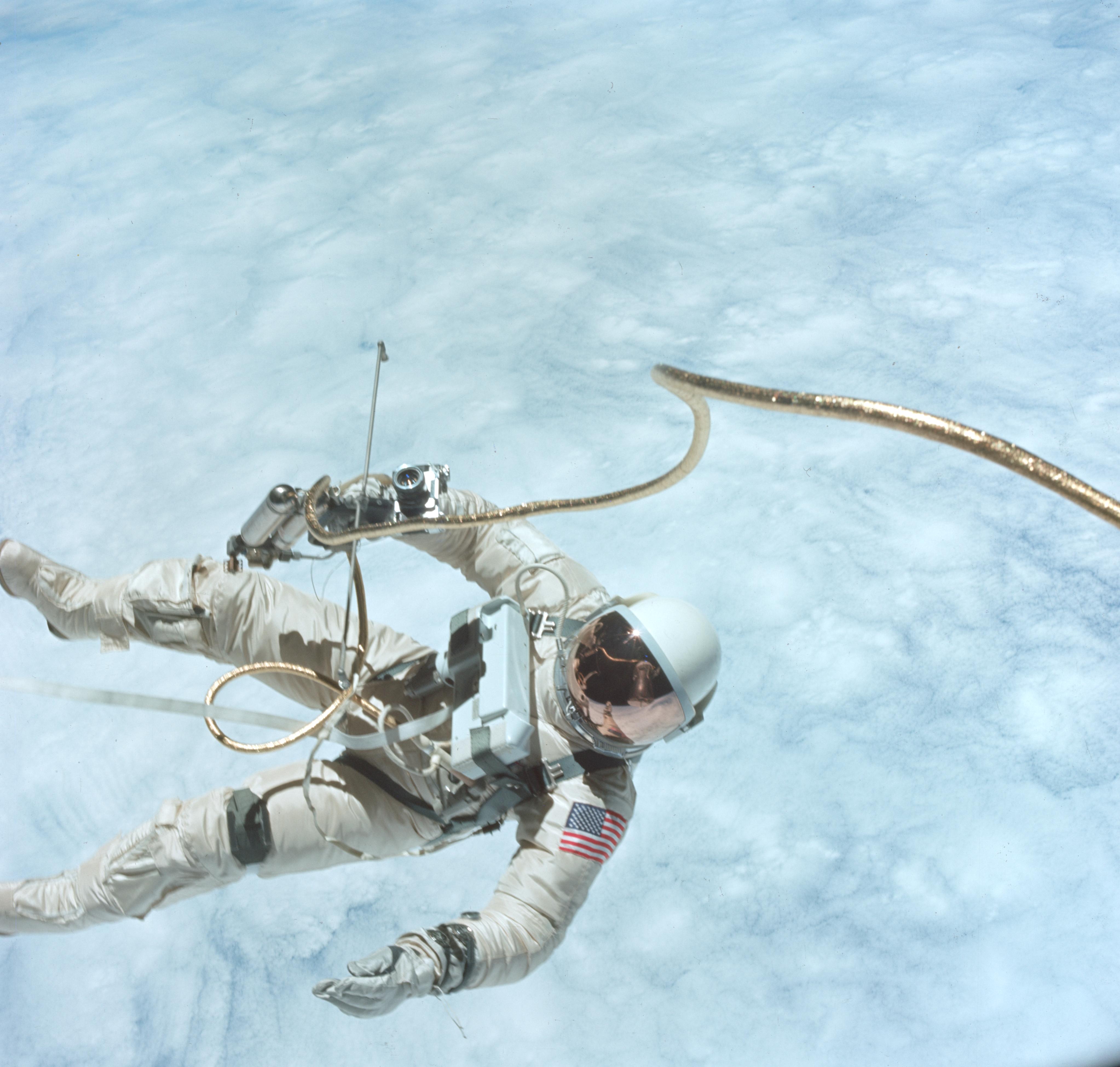
Figure 23: Ed White's EVA on GT-4, photographed by Jim McDivitt. Note the Hand-Held Maneuvering Unit. (NASA archive photo)
Despite press reports, this was not a rendezvous at all, since the two vehicles went into orbit together. Still, NASA assumed GT-4 would be good practice for learning to fly one vehicle in proximity to another.
They were wrong.
With only a brief time to train for the EVA, and no training at all for station-keeping, McDivitt and White blasted into space atop their Titan II launch vehicle. Upon reaching orbit, the Gemini capsule separated from the Titan upper stage.
The Gemini separated from the Titan and moved away, as planned. The Titan, although no longer thrusting, was still “venting” excess propellant, which caused the stage to move away and begin a slow tumble. By the time McDivitt got the Gemini capsule separated and turned around, the upper stage was much farther away than expected.
“I maneuvered over to it, just as we were going into the dark. So now I'm trying to station keep with a maneuvering vehicle. Another thing they did, they put two strobe lights on the stage. Since one light was on each side, I could see only one flashing strobe light. . . . Nobody in their right mind would fly formation with a strobe light in their eyes! It didn't give me any clues at all, it just blinded me. I don't know why the hell they put that on there.”
Over the next couple of orbits, McDivitt tried closing on the Titan, but with no radar and only a single blinking strobe visible during night passes, the task proved impossible.
“We were close to it a number of times, but it kept maneuvering away. And I couldn't tell how close I was or what kind of closing rate . . . I was on the top, bottom, left, right, behind and in front of that tumbling upper stage.
“Finally, I just broke it off; I didn't want to run into it. It wasn't a vital part of the mission.”
Ken Young, a former NASA manager and rendezvous specialist, worked that flight from Mission Control:
The GT-4 story was always a bitter one to us rendezvous guys since the exercise was NOT about rendezvous, but instead a somewhat feeble (and botched) attempt to get a feel for station-keeping/formation-flying as a leg up on the Apollo [missions].
The whole exercise was literally a last minute (a month or so before flight) secret add-on and, regrettably, the NASA PAO (Public Affairs Office) guys used the term “rendezvous” with the press, and all involved got egg on our face! It wasn't a big deal or significant failure to our group but, of course, the press played it up as one.
In their crew debriefing immediately after the flight, commander McDivitt and pilot Ed White described their frustrations:
McDivitt: I watched it, and it looked like it wasn't going away from us any more. . . It was in the window and I could see it. The booster started falling again, descending below us. It actually went out of my view in the window. At the time, though, our relative velocities were quite small . . . So, I allowed myself about another minute and I pitched down and looked for it. It appeared that during that minute it had gone a lot farther down than I had expected it to go.
White: Yes, I was surprised. Remember that it looked like the orbit was surely something different than we predicted.
McDivitt: Yes. It looked to me like the booster and the spacecraft weren't in anything that even resembled the same orbit.
Before McDivitt could fly back to the venting upper stage, the two spacecraft entered the night side of the Earth, plunging them in darkness. With only a single, flashing strobe light for guidance, McDivitt attempted to close on the Titan.
McDivitt: I didn't have any idea in the world where we were. . . . Finally, we could see the sky starting to get a little gray, and I thought at least we were going to get to see where the thing was. And all of a sudden the booster came out, just like that, and you could see it. The lights disappeared and there was the booster. It was two or three miles away, I'll bet.
Running low on propellant (this was only the beginning of a four-day mission), McDivitt tried once more to close on the Titan.
McDivitt: So I aimed behind it, so to speak, and down, and I thrusted that way trying to get enough closing velocity . . . we just didn't gain on it . . . I just absolutely could not get down to the booster. It kept pulling away and pulling away until the time we got to Hawaii.
White: You were putting a lot of delta-V in there, and we just weren't doing anything. We just weren't making any headway.
McDivitt: [T]he only thing we could do would be to leave the booster. The fuel was down to around 75 percent on my gauge. . . . So I made up my mind then that it looked like a hopeless task and that we had better stop this stuff or we were going to lose all the fuel for the whole mission.
The post-flight analysis took months. Back in Houston, Jerome (Jerry) Bell was tasked with the unenviable job of figuring out what had gone wrong. He explains:
The post flight [analysis] was started in real-time immediately after the termination of the station keeping. Management and PAO needed something to give to the media and [the analysis] was going on in parallel with the flight and beyond. We had to take hundreds of pulses and try to model them as best we could. . . I think we stopped after inputting 92 small maneuvers. . . . [The analysis] continued for months, and everything was classified confidential.
Ken Young agrees:
One of our guys, Jerry Bell (who wasn't “in the know” pre-flight), was given the impossible task of post-flight analysis on what went wrong. Bell spent an agonizing six months or so running dozens of scenarios and relative motion plots. A thankless job, for sure.
NASA had learned an important lesson. Station-keeping in space was not as simple as flying jets in formation. Future crews would need to be well versed in the nuances of orbital mechanics before strapping into their seats.
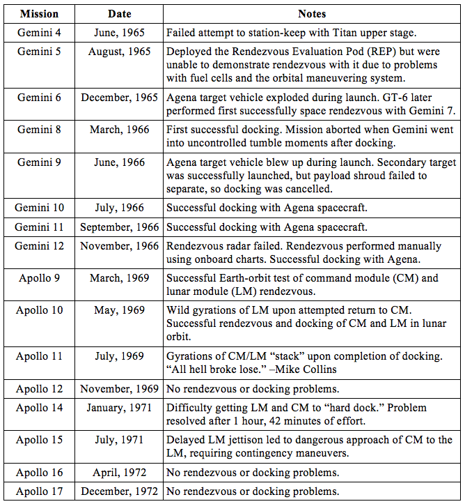
A list of rendezvous flights from Gemini and Apollo show that the lessons took a long time to master.
Table 1: Gemini and Apollo rendezvous missions
STS-41C: “It’s what we should have done in the first place”
Even two decades later, proximity operations continued to surprise NASA.
On STS-41C, the very first space shuttle rendezvous flight, the orbiter Challenger was to rendezvous with the Solar Max satellite, a spacecraft launched in 1980 to study the Sun. The gyroscopes that stabilized the craft had failed, and NASA saw this as an opportunity to show off their new shuttle’s on-orbit repair capability.
According to the mission plan, shuttle commander Bob Crippen would rendezvous with Solar Max. Payload specialist George “Pinky” Nelson would then do an EVA and strap into the Manned Maneuvering Unit (MMU), a powered backpack that would enable him to fly over to the tumbling satellite. Nelson would then use a custom-built device to grab hold of the satellite and use his backpack to stabilize it. He would then return to the shuttle, Crippen would fly over to Solar Max, and another astronaut, Terry Hart, would grab it with the shuttle’s arm. After stowing it in the payload bay, astronauts would perform another spacewalk to replace the malfunctioning gyroscopes, then return Solar Max to orbit to complete its mission.
According to Crippen, the rendezvous phase went perfectly. “Perfect. Just like clockwork.” He adds with a laugh, “[That’s] always amazing when you’re doing something for the first time.”
But the good fortune didn’t continue. When Nelson arrived at Solar Max, he discovered his special docking device wouldn’t latch onto the satellite. Nelson tried several times, each attempt bumping the spacecraft and imparting additional rotation and translation to it. Solar Max began tumbling faster. Nelson even tried grabbing it with his hand and stabilizing it, but to no avail. Finally, the rescue attempt was aborted. Nelson returned to the orbiter and Crippen tried to maneuver Challenger close enough for Hart to grab the spinning satellite with the arm. “I approached the satellite and Terry Hart had the arm ready, but it was tumbling too bad.”
By now, Challenger was dangerously low on maneuvering propellant, particularly in the forward RCS tanks.
“While it was wildly rotating, I definitely burned up more propellant in the forward RCS than I should have. But I didn’t know if there was another method of getting [Solar Max] in. . . . I thought if we didn’t get it, it was lost.” A problem with the shuttle’s digital autopilot (DAP) also led to additional propellant use: every time the orbiter fired jets to maintain attitude, cross-coupling effects pushed the shuttle closer to Solar Max, requiring Crippen to maneuver away. “It tended to ‘walk in’ toward the satellite, so you ended up almost continually popping the jets to stay away from it.”
Mission Control aborted the attempt, and Crippen moved Challenger to a stand-off position for a second-day attempt, something NASA had not foreseen nor rehearsed. Overnight, Solar Max mission controllers were able to stabilize the satellite enough to attempt another approach, and Houston mission control computed a new rendezvous. The next day, low on forward RCS, Crippen re-rendezvoused with Solar Max.
Terry Hart was able to grab the Solar Max with the arm, move it into the bay, and the rest of the repair mission went off as planned.
“It’s what we should have done in the first place, and not used the MMU,” Crippen says, chuckling.
Sometimes, the simplest plan is the best, even at NASA.
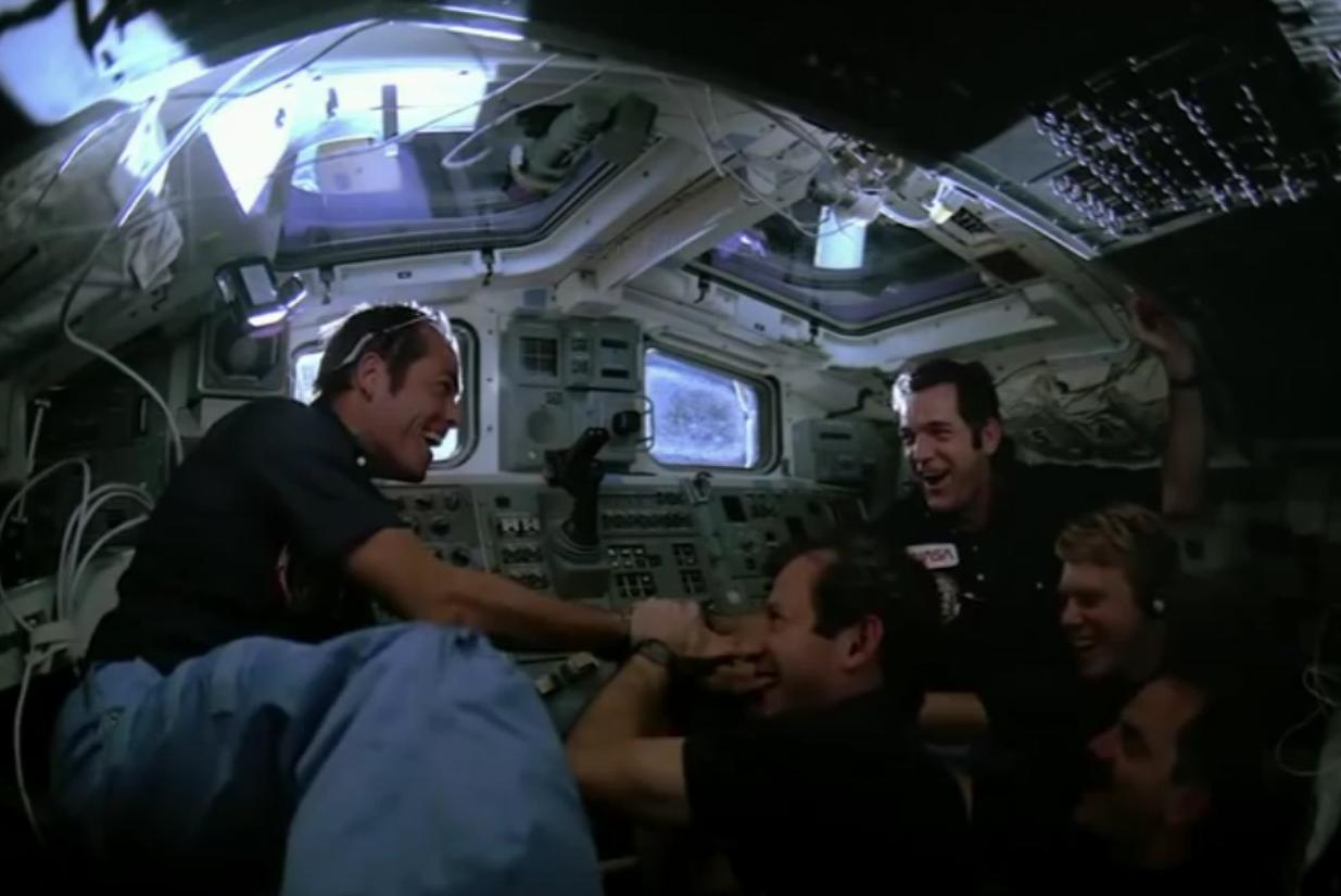
Figure 24: Job well done. STS-41C crew celebrate capture of Solar Max
Glossary
Ascending node: The intersection of a vehicle’s orbital plane with the Earth’s equatorial plane, with orbital motion in a northward (versus southward or “descending”) direction.
Cross coupling: The translation motion caused by a rotational jet firing (and vice versa) caused by misalignment of the maneuvering jets to the vehicle’s body axes and center of gravity.
Delta-V: Change in velocity, caused by maneuvers or forces acting on the vehicle.
Digital Auto Pilot (DAP): Software programs that interpret maneuver requests, such as attitude hold or station-keeping, and generate jet firings to satisfy those requests.
Doppler shift: The compression or stretching of an electromagnetic signal’s wavelength caused by motion toward or away from the observer.
Ephemeris: Essentially, a huge table predicting the positions, velocities, and other data of an object in orbit.
Equatorial orbit: An orbit around the equator, with 0° inclination.
Flight Dynamics Officer (FDO, “Fido”): The front-room Mission Control position responsible for the vehicle’s trajectory, from tower clear until landing and rollout. This includes all rendezvous maneuvers.
Geosynchronous orbit: An orbit with a period of 24 hours. If it is also a circular orbit at 0° inclination, the spacecraft remains fixed over the same spot on the Earth (geostationary orbit). Primarily used for communications satellites.
Inclination: The angle of a satellite’s orbital plane to the Earth’s equator.
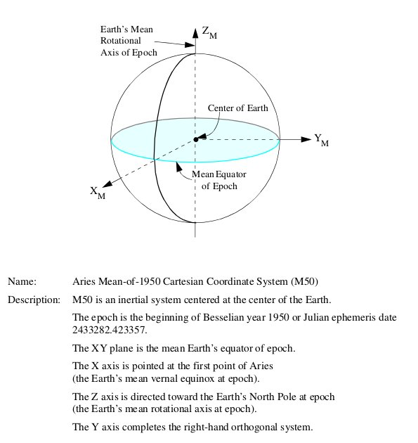
Inertial coordinate system: A non-rotating, essentially fixed (relative to the stars) coordinate system with origin at the center of the Earth.
Figure 25: M50 Inertial coordinate system
(Source: Rendezvous and Proximity Operations Design Reference for the International Space Station)
Inertial Navigation System (INS): Avionics hardware used to calculate estimates of a vehicle’s state (position, velocity, attitude) relative to an inertial coordinate system.
Integrate: Computing the future state of a vehicle given its current state and estimates of future forces acting upon it.
Kalman filter: A mathematical algorithm that uses a series of measurements observed over time to estimate other variables that can’t be directly measured, or cannot be measured accurately.
Launch azimuth: The angle of a vehicle’s launch groundtrack, relative to due east.
Launch window: The time period on launch day during which a vehicle must launch to meet its mission objectives.
Launch window planar pane: The limitation on the launch window caused by the Earth’s rotation and limited by a vehicle’s ascent performance.
Launch window phase pane: The limitation on the launch window caused by rendezvous constraints, such as lighting, communication coverage, or crew work day limits.
Lighting constraints: Limitations imposed by Sun angle. Can impact launch, aborts, landing, on-orbit rendezvous, or approach and docking.
Margin: A vehicle’s capability beyond the minimum required to meet mission requirements, such as extra propellant, payload, time, etc.
Nautical mile: 6076.1155 feet or 1.875 km, approximately one minute of latitude.
Nodal regression: The westward (or eastward) rotation of a satellite’s orbital plane, caused primarily by the oblateness of the Earth.
Nominal: Normal or expected.
Oblateness (Earth): The flattening of the Earth, caused by our planet’s rotation and resulting in a “bulge” around the equator.
Orbital period: The time it takes for one object to complete an orbit around another. In low Earth orbit, this is on the order of ninety minutes.
Phantom plane: The targeted insertion plane for the chaser vehicle which will result in minimal wedge angle difference at rendezvous.
Phase angle: The angle between the chaser and target vehicle, typically measured in the target vehicle’s orbital plane.
Phasing orbit: A chaser vehicle’s orbit, usually at a lower altitude (energy) from the target, causing it to approach the target over time.
Plume impingement: The impact of exhaust gases upon another object.
Range and range rate: The straight-line distance to an object and the rate at which that range is changing.
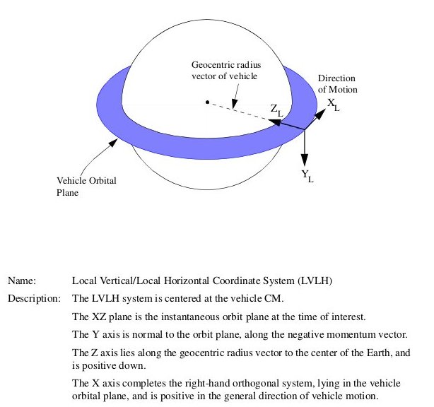
Relative coordinate system: An orthogonal, rotating coordinate system centered at one vehicle (usually the target) with the Z-axis pointing to the center of the Earth, Y-axis along the satellite’s angular momentum vector, and X-axis perpendicular to both, with positive in the direction of orbital travel. For a circular orbit, X is along the velocity vector. Also called an LVLH (local vertical, local horizontal) coordinate system.
Figure 26: Relative coordinate system
(Source: Rendezvous and Proximity Operations Design Reference for the International Space Station)
Relative navigation system: Hardware, such as rendezvous radars or star trackers, used to measure angles, distances, velocities, or attitudes of one vehicle relative to another.
Rendezvous profile: A series of maneuvers designed to bring a vehicle from orbital insertion to the near-proximity of another spacecraft already in orbit.
Rendezvous radar: An active radar system (Ku-band on the shuttle) that determines range and range-rate to the target vehicle. The ISS had no transponder onboard, so this was entirely done by “skin tracking.”
Star tracker: An optical device for keeping an inertial navigation system properly aligned by measuring the positions of stars. Can also be used to track other objects in orbit.
State vector: A set of information describing the position, velocity, and attitude (and possibly rates) of a vehicle at a specific time.
State vector update: A new, more accurate state vector uplinked from the ground to improve the onboard estimate of a vehicle’s state.
Wedge angle: The angle between two orbital planes. A combination of the differences in inclination and ascending node location.
Yaw steering: A technique used during ascent to steer the launch vehicle to the east or west in order to get it into the proper phantom plane.
Zonal and tesseral harmonics: Higher-order effects of the Earth’s non-spherical shape, which perturb the motion of vehicles in orbit.
NOTE: This is the final installment of this two-part article. You can read Part 1 here.
Copyright © 2014 by Terry Burlison
Terry Burlison worked in mission operations at Johnson Space Center in the early days of the space shuttle program. He trained as the first shuttle-era rendezvous Flight Dynamics Officer (FDO), defined the Phase B RTCC (Real Time Computer Complex) rendezvous requirements, and designed rendezvous displays for use in the Mission Control Center. After leaving NASA, he worked for Boeing Aerospace and as a private contractor, developing automated rendezvous techniques for low earth orbit. He finished his career as a private consultant for various companies looking to resupply the International Space Station, including Rocketplane-Kistler, winner of one of the COTS (Commercial Orbital Transportation Systems) contracts in 2006 for ISS resupply. Terry is now a full-time writer, trying to get his articles and novels to rendezvous with his deadlines. You can follow Terry on Twitter at: @ExNASATerry, or post questions about this article on his blog here.


